
27 Feb Zephyr tutorial 104 – Case study: Porting and using SPI flash in Zephyr
Zephyr tutorial 104 – Case study: Porting and using SPI flash in Zephyr

Javad Rahamipetroudi
27/02/2024
Introduction
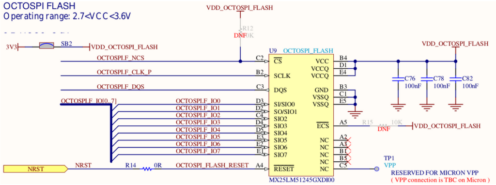
In our previous tutorial, we learned about using the I2C protocol with Zephyr OS. Now, we will show a case study of a higher-level interface: the flash API to access an SPI flash memory. Our device of choice is a SPI flash device known as the MX25LMG, a 512 MBit flash memory device that’s already mounted on the B-U585I-IOT02A development board. The application code for this case study already exists in the Zephyr source under samples/drivers/spi_flash. We will make some modifications to the sample application to suit our needs. As always, the first step is to add the device configuration in the Device Tree file.
Device tree configuration
By looking at the device schematic, we see that the SPI flash memory is connected to the OCTOSPI port. As a result we should add the device configuration to the OCTOSPI bus.
 If we look at the
 b_u585i_iot02a-common.dtsi file, we notice that the SPI flash is already configured and added to the octospi2 bus:
&octospi2 {
    pinctrl-0 = <&octospim_p2_clk_pf4 &octospim_p2_ncs_pi5
                 &octospim_p2_io0_pf0 &octospim_p2_io1_pf1
                 &octospim_p2_io2_pf2 &octospim_p2_io3_pf3
                 &octospim_p2_io4_ph9 &octospim_p2_io5_ph10
                 &octospim_p2_io6_ph11 &octospim_p2_io7_ph12
                 &octospim_p2_dqs_pf12>;
    pinctrl-names = "default";

    status = "okay";

    mx25lm51245: ospi-nor-flash@0 {
        compatible = "st,stm32-ospi-nor";
        reg = <0>;
        ospi-max-frequency = <DT_FREQ_M(50)>;
        size = <DT_SIZE_M(512)>; /* 64 MBytes */
        spi-bus-width = <OSPI_OPI_MODE>;
        data-rate = <OSPI_DTR_TRANSFER>;
        four-byte-opcodes;
        status = "okay";

        partitions {
            compatible = "fixed-partitions";
            #address-cells = <1>;
            #size-cells = <1>;

            partition@0 {
                reg = <0x00000000 DT_SIZE_M(64)>;
            };
        };
    };
};
Based on the configuration file, the bus frequency is configured as 50MHz and Flash size is also set as 64MBytes. Furthermore, the whole device is partitioned as a single cell with 64MB of size.
In order to use the flash device in a platform-independent way, we also should assign an alias to it. Thus it is possible to use the SPI flash device as “spi-flash0” in the code. This is also already done in the aliases section of the device tree:
aliases {
    watchdog0 = &iwdg;
    spi-flash0 = &mx25lm51245;
    ...
};
To enable DMA channels for the SPI device, We should check the STM32U585xx datasheet and find the corresponding DMA channels for the external memory access. According to the datasheet, we should enable the channel 14,15 for transfer to/from eternal memories:
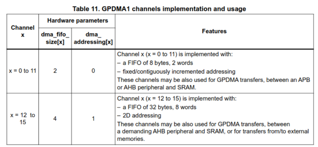
The DMA channel is defined in the board overlay file as follows:
&octospi2 {
    /* channel 12-15 are for transfers to/from external memories */
    dmas = <&gpdma1 12 41 0x10480>; /* request 41 for OCTOSPI2 */
    dma-names = "tx_rx";
};
Project configuration
To use the SPI flash, we must enable the SPI flash interface and also FLASH configuration in the project configuration file (prj.conf):
CONFIG_STDOUT_CONSOLE=y
CONFIG_FLASH=y
CONFIG_SPI=y
Coding
As usual the first step is adding the required headers and then identifying the device in the code. To do this, we should include the flash.h header file, alongside with the other header files that we need.
#include <zephyr/kernel.h>
#include <zephyr/drivers/flash.h>
#include <zephyr/device.h>
#include <zephyr/devicetree.h>
Device Initialization
Next we introduce the SPI flash device based on the assigned name in the aliases section of the device tree:
const struct device *flash_dev = DEVICE_DT_GET(DT_ALIAS(spi_flash0));
All the flash APIs use an absolute address within the flash. It is the responsibility of the application code to assign meaning to these addresses. Typically your application will define different areas and addresses for different purposes. There is also a flash_map API that makes use of partitions defined in the device tree to make abstraction of those areas, but for this tutorial that goes a bit too far. Instead, we define the base address that we will use with a macro. The SPI flash is not used for anything else so we can use address 0x00000 as base address.
#define SPI_FLASH_TEST_REGION_OFFSET 0x00000
Some flash operations, like erase, need to be performed on a full sector. We can find the sector size in the device data sheet, it is 4096 bytes for this device. It is possible to retrieve this information from the flash itself with the flash_get_parameters function; however, for this tutorial, it’s simpler to declare it statically. So, we define the sector size as below:
#define SPI_FLASH_SECTOR_SIZE 4096
Before using the device we should make sure that the device is ready to use:
if (!device_is_ready(flash_dev)) {
        printk("%s: device not ready.\n", flash_dev->name);
        return 0;
}
Erase device
Next, we erase the region that we defined above by using the flash_erase function, that is defined as follows:
int flash_erase(const struct device *dev, off_t offset, size_t size)
So, we will need the device, offset and the size to erase (which has to be a multiple of the sector size) to invoke the command.
rc = flash_erase(flash_dev, SPI_FLASH_TEST_REGION_OFFSET,
                 SPI_FLASH_SECTOR_SIZE);
if (rc != 0) {
    printf("Flash erase failed! %d\n", rc);
} else {
    printf("Flash erase succeeded!\n");
}
Write
To write into the flash device, we need to use the write function that is declared as follows:
int flash_write(const struct device *dev, off_t offset, const void *data, size_t len)
We also need to to define a simple buffer to write to the buffer:
const uint8_t wr_buf[] = { 'H', 'E', 'L','L','O'};
const size_t buf_len = sizeof(wr_buf);
We can write into the SPI flash device as follows:
rc = flash_write(flash_dev, SPI_FLASH_TEST_REGION_OFFSET, wr_buf, buf_len);
if (rc != 0) {
    printf("Flash write failed! %d\n", rc);
    return -1;
}
Read
To verify that the write operation was successful, let’s read from the device. The read function is declared as follows:
int flash_read(const struct device *dev, off_t offset, void *data, size_t len)
As we can see, the function signature is exactly same as the write function, except that the *data parameter is not constant.
Let’s read from the same location that we wrote the wr_buf:
uint8_t rx_buf[32] = {0};
rc = flash_read(flash_dev, SPI_FLASH_TEST_REGION_OFFSET, rx_buf, buf_len);
if (rc != 0) {
    printf("Flash read failed! %d\n", rc);
    return -1;
}

if (memcmp(rx_buf, wr_buf, buf_len) == 0) {
    printf("Data read matches data written: %s. Good!!\n", buf);
} else {
    printf("OOPS, there are some mismatch in write/read operation\r\n");
}
Full source code
#include <zephyr/kernel.h>
#include <zephyr/drivers/flash.h>
#include <zephyr/device.h>
#include <zephyr/devicetree.h>
#include <stdio.h>
#include <string.h>

#define SPI_FLASH_TEST_REGION_OFFSET 0x00000
#define SPI_FLASH_SECTOR_SIZE        4096

int main(void)
{
  const struct device *flash_dev = DEVICE_DT_GET(DT_ALIAS(spi_flash0));
  int rc = 0;
  if (!device_is_ready(flash_dev)) {
    printk("%s: device not ready.\n", flash_dev->name);
    return 0;
  }

  rc = flash_erase(flash_dev, SPI_FLASH_TEST_REGION_OFFSET,
                   SPI_FLASH_SECTOR_SIZE);
  if (rc != 0) {
    printf("Flash erase failed! %d\n", rc);
  } else {
    printf("Flash erase succeeded!\n");
  }

  printf("Test Write operation...\n");
  const uint8_t wr_buf[] = { 'H', 'E', 'L','L','O'};
  const size_t buf_len = sizeof(wr_buf);

  rc = flash_write(flash_dev, SPI_FLASH_TEST_REGION_OFFSET, wr_buf, buf_len);
  if (rc != 0) {
    printf("Flash write failed! %d\n", rc);
    return -1;
  } else {
    printf("Data write OK!...\n");
  }

  printf("Read operation...\n");
  uint8_t rx_buf[32] = {0};
  rc = flash_read(flash_dev, SPI_FLASH_TEST_REGION_OFFSET, rx_buf, buf_len);
  if (rc != 0) {
    printf("Flash read failed! %d\n", rc);
    return -1;
  }

  if (memcmp(rx_buf, wr_buf, buf_len) == 0) {
    printf("Data read matches data written: %s. Good!!\n", rx_buf);
  } else {
    printf("OOPS, there are some mismatch in write/read operation\r\n");
  }

  return 0;
}
Sample output
*** Booting Zephyr OS build zephyr-v3.5.0-2706-gede9b0337c72 ***
Flash erase succeeded!
Test Write operation...
Data write OK!...
Read operation...
Data read matches data written: HELLO. Good!!
Conclusion
In this tutorial, we demonstrated the use of the Zephyr flash API to access an external SPI flash device. As you can see, most of the complex details are abstracted away from the developer. In addition, the details of the specific board hardware are isolated in the device tree and don’t need to be explicit in the source code. However, it is important to keep in mind that this sample is just a demonstration example. In order to have a fully functional system, there are numerous detailed constraints that need to be taken into consideration.
Presentations