
15 Feb Zephyr tutorial 103 – Case Study: Reading from VEML6030 light sensor
Zephyr tutorial 103 – Case Study: Reading from VEML6030 light sensor

Javad Rahamipetroudi
14/02/2024
In this case study we are going to develop a simple application to read from the VEML6030 light sensor that is already mounted on the B-U585I-IOT02A board. According to the data-sheet, VEML6030 is a high accuracy ambient light digital sensor in a 2 mm x 2 mm package. The communication interface with this sensor is based on the I2C protocol, and the ambient light result is available as a digital value.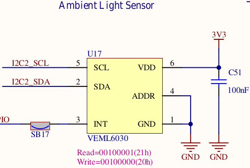
Device tree
Since we’re talking about devices on the board, we start by looking at the device tree. The default DT for the B-U585I-IOT02A board doesn’t include the configuration of VEML6030, so we have to add it to the overlay file in our project. According to the schematic, the light sensor is connected to the I2C2 bus. Therefore, we should define our device as an I2C2 sub-node.
As we have done in the last tutorial, we create a b_u585i_iot02a.overlay file in the board directory, and we define the light sensor sub-node as follows:
&i2c2 {
	veml6030:veml6030@10 {
		compatible = "vishay,veml6030";
		reg = <0x10>;
		label = "Ambient Light Sensor";
		status = "okay";
	};
	status = "okay";
};
According to the data-sheet, the VME6030 sensor has two possible addresses: with the ADDR pin connected to VCC, the address will be 0x48; otherwise, the address will be 0x10. According to the schematic, ADDR is connected to GND so the device’s slave address will be 0x10.
Now, let’s build the application and see whether everything is OK or not:
west build --force -p always -b b_u585i_iot02a app/
If no error is reported, then it means that our configuration is working fine.
Now, it’s time to write a simple application for the sensor.
A simple application to read from VME6030 sensor
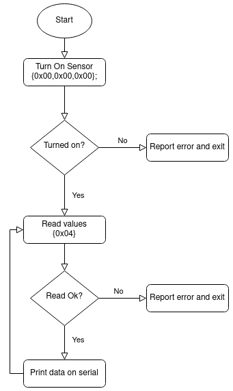 In order to develop our simple application, first we need to include our required files. The flowchart on the right depicts the required steps to read from the sensor.
Now, let’s do some coding!
First, we must include the necessary header files:
#include <zephyr/kernel.h>
#include <zephyr/drivers/i2c.h>
Next, we must find the device tree node for the light sensor:
#define VEML6030_NODE DT_NODELABEL(veml6030)
Notice that the DT_NODELABEL looks for the device based on the node label we passed to it. In this case, the node label is veml6030. We could also hard-code the bus number and device address in the application code, but relying on the device tree gives us more flexibility to use the same application code on different boards.
For the next step, we can get the device configuration with I2C_DT_SPEC_GET macro. We need this structure to communicate with the device.
static const struct i2c_dt_spec dev_i2c = I2C_DT_SPEC_GET(VEML6030_NODE);
Before accessing the bus, we must make sure that the bus is ready for use:
int main(int argc, char** argv)
{
    int ret = 0;
    if (!device_is_ready(dev_i2c.bus)) {
        printk("I2C bus %s is not ready!\n\r",dev_i2c.bus->name);
        return;
    }
...
Now we can follow the flow chart above. The first step is to turn the device on by writing three 0 bytes to it.
  uint8_t vme_turnon[3] = {0x00,0x00,0x00};
  ret = i2c_write_dt(&dev_i2c, vme_turnon, 3);
  if(ret != 0) {
    printk("Failed to turn on VEML6030 Light sensor. Address %x at reg. %x n",
           dev_i2c.addr, vme_turnon[0]);
  }
Now, we can read the ambient light data from register 0x04:
  uint8_t sensor_read[1] = {0x04};
  uint8_t temp_reading[2]= {0};
  while(1) {
    ret = i2c_write_read_dt(&dev_i2c,&sensor_regs[0],1,&temp_reading[0],2);
    if(ret != 0) {
    	printk("Failed to write/read I2C device address %x at Reg. %x n",
              dev_i2c.addr,sensor_regs[0]);
    }
    else {
      printk("Sensor data: %d %d\r\n", temp_reading[0], temp_reading[1]);
    }
  }
That’s all. Now, we can build the app and flash the board. Let’s open the /dev/ttyACM0 terminal and check the output values from the sensor.
*** Booting Zephyr OS build v3.6.0-rc2-95-gd93693082aba ***
Ambient light value: 540
Ambient light value: 543
Ambient light value: 543
Ambient light value: 542
Ambient light value: 541
Ambient light value: 568
Ambient light value: 226
Ambient light value: 218
Ambient light value: 216
Ambient light value: 230
Ambient light value: 230
Conclusion
This tutorial shows how to access a very simple device from the application code, while still making some abstraction of the hardware. In the next instalment, we’ll look at a slightly more complex device, a SPI flash.
Presentations