
25 Jan Zephyr tutorial 102 – Device tree
Zephyr tutorial 102 – Device tree

Javad Rahamipetroudi
24/01/2024
So far we have learned how to print a simple Hello World application into the serial output. However, any microcontroller without peripherals is a useless device. In this tutorial, we will learn how to introduce various types of peripherals in our project.
Device tree
As it is stated in the Devicetree documentation page in Linux kernel docs:
“The DT was originally created by Open Firmware as part of the communication method for passing data from Open Firmware to a client program (like to an operating system). An operating system used the Device Tree to discover the topology of the hardware at runtime, and thereby support a majority of available hardware without hard coded information (assuming drivers were available for all devices).”
However, after a while due to its flexibility and power, it found its place in the world of embedded systems.
Zephyr uses the device tree concept to manage peripherals in a board or MCU. Just consider a device description header file for a typical MCU (in this case STM32):
/* Internal SRAMs size */
#define SRAM1_SIZE               (0x30000UL)    /*!< SRAM1=192k */
#define SRAM2_SIZE               (0x10000UL)    /*!< SRAM2=64k  */
#define SRAM3_SIZE               (0x80000UL)    /*!< SRAM3=512k */
#define SRAM4_SIZE               (0x04000UL)    /*!< SRAM4=16k  */

/* External memories base addresses - Not aliased */
#define FMC_BASE                 (0x60000000UL) /*!< FMC base address                                   */
#define OCTOSPI2_BASE            (0x70000000UL) /*!< OCTOSPI2 memories accessible over AHB base address */
#define OCTOSPI1_BASE            (0x90000000UL) /*!< OCTOSPI1 memories accessible over AHB base address */

#define FMC_BANK1                FMC_BASE
#define FMC_BANK1_1              FMC_BANK1
#define FMC_BANK1_2              (FMC_BANK1 + 0x04000000UL)

/* Flash, Peripheral and internal SRAMs base addresses - Non secure */
#define FLASH_BASE_NS            (0x08000000UL) /*!< FLASH (up to 2 MB) non-secure base address         */
#define SRAM1_BASE_NS            (0x20000000UL) /*!< SRAM1 (192 KB) non-secure base address             */
#define SRAM2_BASE_NS            (0x20030000UL) /*!< SRAM2 (64 KB) non-secure base address              */
#define SRAM3_BASE_NS            (0x20040000UL) /*!< SRAM3 (512 KB) non-secure base address             */
#define SRAM4_BASE_NS            (0x28000000UL) /*!< SRAM4 (16 KB) non-secure base address              */
#define PERIPH_BASE_NS           (0x40000000UL) /*!< Peripheral non-secure base address                 */
This excerpt of header code from stm32u585xx.h looks familiar to most developers who have worked with MCUs.
Now, consider you are developing a code that the final hardware is not (fully) specified yet. For example, we are not sure on which MCU the application will be deployed. If we develop the code based on specific hardware, we are in trouble. So, what is the solution?
That is where Zephyr comes in. It uses a device tree and driver API to make an isolation layer between the application and the underlying hardware. In this case, rather than adapting our application for different hardware, we describe the hardware specs in a DT format file. We write only one version of the application using Zephyr’s generic headers. The magic happens with the build command: you specify which application to build, and to which target hardware.
Let’s consider a basic DT for the B-U585I board:
/dts-v1/;
#include "b_u585i_iot02a-common.dtsi"

/ {
    model = "STMicroelectronics B-U585I-IOT02A discovery kit";
    compatible = "st,b-u585i-iot02a";

    chosen {
        zephyr,console = &usart1;
        zephyr,shell-uart = &usart1;
        zephyr,sram = &sram0;
        zephyr,flash = &flash0;
        zephyr,code-partition = &slot0_partition;
    };

    aliases {
        led0 = &green_led_1;
        led1 = &red_led_1;
        sw0 = &user_button;
    };
};

&flash0 {
    partitions {
        compatible = "fixed-partitions";
        #address-cells = <1>;
        #size-cells = <1>;
        boot_partition: partition@0 {
            label = "mcuboot";
            reg = <0x00000000 DT_SIZE_K(64)>;
        };
        slot0_partition: partition@10000 {
            label = "image-0";
            reg = <0x00010000 DT_SIZE_K(416)>;
        };
.
.
.
    };
};
As we can see, rather than hardcoding the hardware specs into our application body, we put it in a human-readable format.
Now, just consider that we have designed a custom IoT board that has different types of sensors and actuators. We call it Mindboard. The Mindboard has the following specs: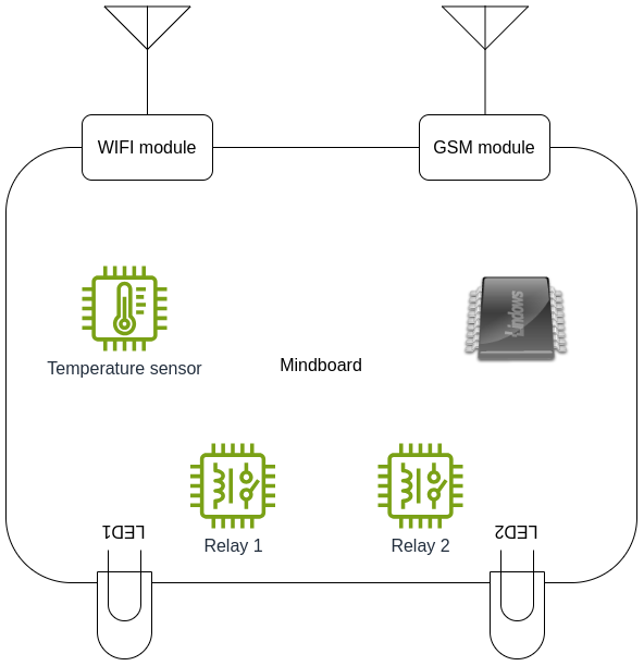
- An I2C based Temperature sensor
- An I2C EEPROM
- A SPI WiFi module
- Two LED indicators
- Two relay actuators
Now, let’s write a simple device tree for the Mindboard. First, create a file with your board name and .overlay extension in the board directory of your project. In our case, it will be b_u585i_iot02a.overlay because the Mindboard was designed based on the B-U585I-IOT02 development kit. Ideally we should create a custom board rather than an overlay, but an overlay is a very quick way to get started.
Humidity sensor
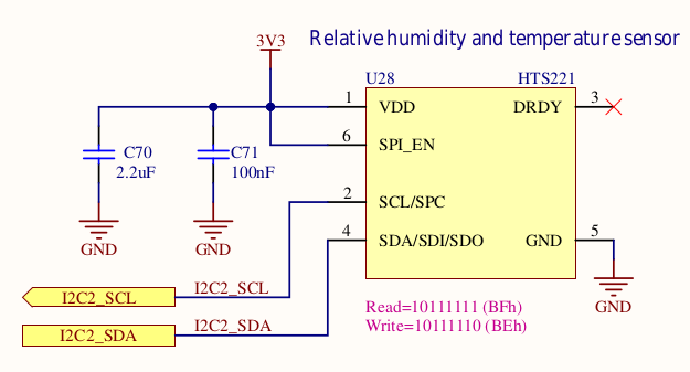 Let’s start with the Humidity sensor. According to the circuit diagram, the HTS221 sensor is connected to I2C2. Furthermore, according to the datasheet, the sensor slave address is 0x5f. (Note that the address we need to use here doesn’t include the R/W bit.) So we added the sensor configuration file as follows:
/ {
    &i2c2 {
        hts221@5f {
            compatible = "st,hts221";
            reg = <0x5f>;
            status = "okay";
        };
    };
};
Flash memory
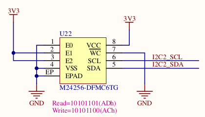 Next, we will add the EEPROM flash memory. According to the schematic, the flash memory is also connected to the I2C. Furthermore, E0 is connected to ground while E1 and E2 are connected to VCC.
To calculate the device slave address, we can refer to the below table from the M24256 datasheet. Dropping the R/W bit, this gives us 0x56 as address.
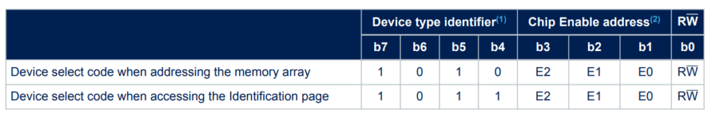
Please note that we need the compatible string field to point which device is going to be used with this driver. In this case, we are using the M24256-DF from STMicroelectronics, which is compatible with the AT24.
aliases {
eeprom-0 = &eeprom0;
};

&i2c2 {
    eeprom0:e2prom@56 {
            	compatible = "atmel,at24";
            	reg = <0x56>;
            	status = "okay";
            	size = <32768>;
            	pagesize = <64>;
            	address-width = <16>;
            	timeout = <5>;
    	};

};
WiFi module
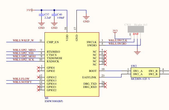 Now, we will add the WiFi SPI module. By looking at the schematic, we see that the wireless module is connected to SPI2.
In the below device tree, we have defined the pin controllers for the SPI2 and also the chip select pin. There is only a single slave device on this SPI bus so we can just use reg=<0> to identify the slave. If more SPI devices are connected to the bus, their corresponding PIN number should be added to cs-gpios of the bus, and the reg field of each module should be set accordingly.
&spi2 {
        pinctrl-0 = <&spi2_nss_pb12 &spi2_sck_pd1
                     &spi2_miso_pd3 &spi2_mosi_pd4>;
        cs-gpios = <&gpiof 12 (GPIO_ACTIVE_LOW | GPIO_PULL_UP)>;
        pinctrl-names = "default";
        status = "okay";

        wifi: wifi@0 {
             compatible = "mxchip,emw3080";
             label = "WIFI Module";
             reg = <0>;

             spi-max-frequency = <4000000>;
     };
};
LEDs
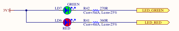 The two LEDs can be simply enabled by gpios:
leds {
    compatible = "gpio-leds";
    green_led_1: led_1 {
        gpios = <&gpioh 7 GPIO_ACTIVE_LOW>;
        label = "User LD7";
    };
    red_led_1: led_3 {
        gpios = <&gpioh 6 GPIO_ACTIVE_LOW>;
        label = "User LD6";
    };
};
The pins PH6 and PH7 are already configured as GPIO by default, so no pinctrl setting is needed.
Relays
Assuming that the two Relays are connected to the GPIO pins PH10, PH11, we modify the device tree overlay as follows:
/ {
        relays {
                compatible = "gpio-relays";
                door_relay: rel_1 {
                        gpios = <&gpioh 10 GPIO_ACTIVE_LOW>;
                        label = "Entrance door relay";
                };
                light_relay: rel_2 {
                        gpios = <&gpioh 11 GPIO_ACTIVE_LOW>;
                        label = "Light relay";
                };
        };
};
Conclusion
With the device tree, it is easy to specify what the board looks like. The syntax takes a little getting used to, but there are plenty of examples that can be used as inspiration. Also, the device tree properties that can be set for each device are very well documented.
The actual code to use the device is isolated in a device driver, which is matched using the compatible string. Often a device driver already exists, and the Zephyr application only needs to use the generic API to access the device. In the next example, we will show an example of that using a light sensor.
Presentations