04 Apr Zephyr tutorial 106 – Porting a new board
Zephyr tutorial 106 – Porting the STM32WB55MMG module to Zephyr

Javad Rahamipetroudi
04/04/2024
Introduction
In the previous tutorial, we discovered how to utilize the BLE stack on the B-U585I-IOT02A board with vendor-specific demos. However, our ultimate objective is to broaden our understanding of Zephyr. In this tutorial, we will be leveraging Zephyr with our development board to achieve this goal. We will explore the incredible Bluetooth-based connectivity capabilities provided by Zephyr. As with the previous tutorial, we will begin by consulting the Zephyr documentation page.
BLE in Zephyr
One of the biggest advantages of Zephyr in comparison with other microcontroller operating systems are its broad connectivity options. Its BLE stack provides the following capabilities:
- Bluetooth v5.3 compliant (SIG qualified).
- Bluetooth Low Energy (BLE) Controller support (i.e. the Zephyr application acts as a BLE Controller device for a host connected over e.g. UART).
- Bluetooth Host support (i.e. the Zephyr application uses a Bluetooth controller device).
- LE Audio in Host and Controller.
To review the full features of BLE in Zephyr, take a look at its Overview page.
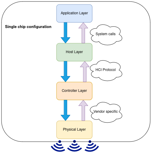
 As we know from the last tutorial, a complete BLE stack contains the following layers:
- Host: This layer provides the required functionalities for our applications. For example, we can compare it with the Linux socket APIs that is provided by the Linux kernel to work with network stack. It provides some network/transport protocols to make an endpoint communication with the peers. The host layer communicates with its lower layer (the Controller layer) through the standardized host controller interface protocol (HCI).
- Controller: This layer implements the link layer protocol, which grantees reliable package transmission, handles all packet transmission/reception and as well handling control procedure.
- Radio: This layer provides all analog/digital required hardware for baseband and passband communication over the air.
The figure on the side depicts the layers included in a typical BLE application.
BLE configurations in Zephyr
Zephyr has the flexibility to run in two modes:
- Single chip configuration
- Dual chip configuration
In the single chip configuration, all of the BLE tasks are done within a single chip. In other words, the application, Host layer and Link layer all reside in the same chip. In this architecture, the Host layer communicate with the Link layer with shared memory message passing. It still uses the HCI protocol internally.
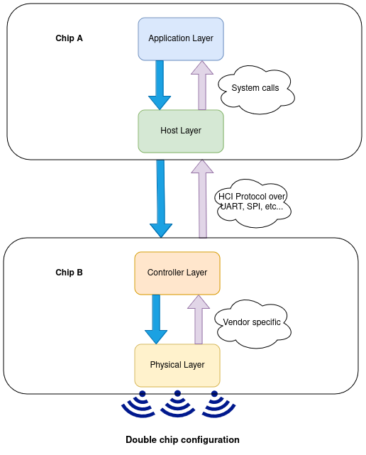
However, in dual chip configuration we have to separate chips. In this case, one chip is responsible for the application and Host layer and another chip is dealing with the Link layer. The two chips communicate over UART, SPI or any other well defined hardware interface; they are otherwise completely independent of each other. Zephyr may run on either or both of the chips.
BLE architecture in B-U585I-IOT02A board
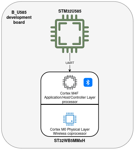
As we have seen in the previous tutorial, the B-U585I-IOT02A board utilizes the STM32WB5MMxH wireless module for its BLE communication. As a result, we have three microcontrollers on the development board. The first one is our main MCU (U585) which is connected to the BLE module with a UART interface. The STM32WB5MMxH module contains two microcontrollers: a Cortex M4F MCU that can run user code (which may or may not include the application, Host and Controller layers), and a Cortex M0 wireless co-processor that handles the Physical Layer. The below figure depicts a high level view of the board.
The Cortex M4F of the STM32WB5MMxH can run a full application + Host + Controller Zephyr stack. However, for this demonstration, we will choose to use the dual-chip configuration and put only the Controller Layer on the Cortex M4F, while the Host Layer and application code will run on the U585.
Based on this architecture, we need three different firmware images; Application (U585 MCU), Controller (Cortex M4F) and Wireless co-processor (Cortex M0) . STMicroelectronics provides the prebuilt binary firmware for the wireless co-processor. However, we have to develop the firmware images for the Cortex M4F and the U585.
The Zephyr OS provides a feature rich Host Layer which we can use for the U585. Furthermore, for the application firmware, we can use all of the existing sample applications provided by Zephyr OS. For the Cortex M4F, we can use Zephyr’s Controller Layer implementation and the hci_uart sample application.
As a conclusion, we need the following images:
- A Controller only Zephyr build for Cortex M4F processor.
- A Host + application build for STM32U585 application processor.
- A prebuilt binary for the wireless co-processor.
Board support package for STM32WB5MMxH
Zephyr OS provides the hci_uart sample application that implements the controller-side HCI layer that we can use for the Cortex M4F. However, there is no board support package for this board. (At least, there wasn’t before we contributed it. Note that since then, Zephyr has switched to “Hardware model version 2”, which causes slight changes. The text below follows hwm2 and is therefore different from the original contribution.) We have to add required board support for the STM32WB5MM Bluetooth module first, before being able to use it as an HCI layer. Note that although the STM32WB5MM is a module that is meant to be integrated on another board, from the Zephyr point of view it is still treated as a separate board when it comes to generating a firmware image for it.
The closest family to this module is nucleo_wb55rg development board, which has the same STM32WB55VGY MCU. So, we will make a copy from this board, in boards/st/ directory and rename it to stm32wb5mmg, then we modify it based on STM32WB5MMxH board.
For the first step, we modify the board description file stm32wb5mmg.yaml as follows. We update identifier and name to match the new board. We also remove the peripherals for which the STM32WB5MMxH module has no pins: i2c, spi, pwm, adc, nvs.
identifier: stm32wb5mmg
name: ST STM32WB5MMG Ultra-low-power Module
type: mcu
arch: arm
toolchain:
  - zephyr
  - gnuarmemb
  - xtools
ram: 256
flash: 1024
supported:
  - gpio
  - dma
  - uart
  - usb_device

vendor:st
Next, we modify Kconfig.defconfig as follows:
# STM32WB5MMG Bluetooth module board configuration

# Copyright (c) 2024 Javad Rahimipetroudi <javad.rahimipetroudi@mind.be>
# SPDX-License-Identifier: Apache-2.0

if BOARD_STM32WB5MMG

choice BT_HCI_BUS_TYPE
        default BT_STM32_IPM
        depends on BT
endchoice

endif
and Kconfig.stm32wb5mmg as follows:
# Copyright (c) 2024 Javad Rahimipetroudi <javad.rahimipetroudi@mind.be>
# SPDX-License-Identifier: Apache-2.0

config BOARD_STM32WB5MMG
        select SOC_STM32WB55XX
board.cmake should also be modified based on the MCU type (in our case stm32wb55vgyx)
# SPDX-License-Identifier: Apache-2.0
board_runner_args(pyocd "--target=stm32wb55vgyx")
board_runner_args(stm32cubeprogrammer "--port=swd" "--reset-mode=hw")

include(${ZEPHYR_BASE}/boards/common/stm32cubeprogrammer.board.cmake)
include(${ZEPHYR_BASE}/boards/common/openocd.board.cmake)

include(${ZEPHYR_BASE}/boards/common/pyocd.board.cmake)
Device tree configuration for STM32WB5MMG
The most important part is modifying the device tree based on the Bluetooth module.
/*
 * Copyright (c) 2024 Javad Rahimipetroudi <javad.rahimipetroudi@mind.be>
 *
 * SPDX-License-Identifier: Apache-2.0
 */

/dts-v1/;
#include <st/wb/stm32wb55Xg.dtsi>
#include <st/wb/stm32wb55vgyx-pinctrl.dtsi>
#include <zephyr/dt-bindings/input/input-event-codes.h>

/ {
        model = "STMicroelectronics STM32WB5MMG Bluetooth module";
        compatible = "st,stm32wb5mmgh6";

        chosen {
                zephyr,console = &usart1;
                zephyr,shell-uart = &usart1;
                zephyr,bt-mon-uart = &lpuart1;
                zephyr,bt-c2h-uart = &lpuart1;
                zephyr,sram = &sram0;
                zephyr,flash = &flash0;
                zephyr,code-partition = &slot0_partition;
        };
};

&clk_hse {
        status = "okay";
};

&clk_lse {
        status = "okay";
};

&clk_hsi48 {
        status = "okay";
};

&clk48 {
        /* Node is disabled by default as default source is HSI48 */
        /* To select another clock, enable the node */
        clocks = <&rcc STM32_SRC_HSI48 CLK48_SEL(0)>;
};

&rcc {
        clocks = <&clk_hse>;
        clock-frequency = <DT_FREQ_M(32)>;
        cpu1-prescaler = <1>;
        cpu2-prescaler = <1>;
        ahb4-prescaler = <1>;
        apb1-prescaler = <1>;
        apb2-prescaler = <1>;
};

&usart1 {
        pinctrl-0 = <&usart1_tx_pb6 &usart1_rx_pb7>;
        pinctrl-names = "default";
        current-speed = <115200>;
        status = "okay";
};

&lpuart1 {
        pinctrl-0 = <&lpuart1_tx_pa2 &lpuart1_rx_pa3>;
        pinctrl-names = "default";
        current-speed = <100000>;
        status = "okay";
};

&adc1 {
        pinctrl-0 = <&adc1_in3_pc2>;
        pinctrl-names = "default";
        st,adc-clock-source = <SYNC>;
        st,adc-prescaler = <4>;
        status = "okay";
};

zephyr_udc0: &usb {
        status = "okay";
        pinctrl-0 = <&usb_dm_pa11 &usb_dp_pa12>;
        pinctrl-names = "default";
};

&flash0 {
        partitions {
                compatible = "fixed-partitions";
                #address-cells = <1>;
                #size-cells = <1>;

                /*
                 * Configure partitions while leaving space for M0 BLE f/w
                 * Since STM32WBCube release V1.13.2, only _HCIOnly_ f/w are supported.
                 * These FW are expected to be located not before 0x080DB000
                 * Current partition is using the first 876K of the flash for M4
                 */

                boot_partition: partition@0 {
                        label = "mcuboot";
                        reg = <0x00000000 DT_SIZE_K(48)>;
                };
                slot0_partition: partition@c000 {
                        label = "image-0";
                        reg = <0x0000c000 DT_SIZE_K(400)>;
                };

        };
};
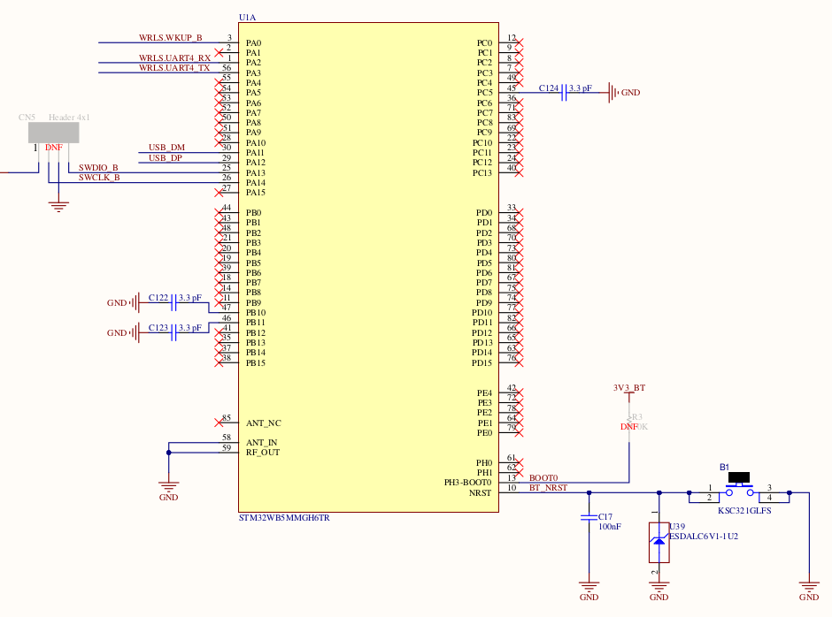
There are some important consideration regarding to wiring between between the main MCU and the Bluetooth module. In general, hardware flow control is required for HCI communication. However, the RTS/CTS pins are not wired on the B-U585I-IOT02A board. As a result, we have to disable hardware flow control in device tree configuration:
&lpuart1 {
	pinctrl-0 = <&lpuart1_tx_pa2 &lpuart1_rx_pa3>;
	pinctrl-names = "default";
	current-speed = <100000>;
	status = "okay";
};
As another point, the baud-rate works best when it is set on 100000 bps.
Now, we are ready to build the Host layer from Zephyr (hci_uart) for our Bluetooth module.
To do this, we do it as follows:
west build --force -p always -b stm32wb5mmg samples/bluetooth/hci_uart
If everything goes well, we should see the build summary:
-- Zephyr version: 3.5.99 (/home/javad/zephyrproject/zephyr), build: zephyr-v3.5.0-2706-gede9b0337c72
[165/166] Linking C executable zephyr/zephyr.elf
Memory region         Used Size  Region Size  %age Used
           FLASH:       39984 B       808 KB      4.83%
             RAM:       19912 B       192 KB     10.13%
           SRAM1:        2908 B        10 KB     28.40%
           SRAM2:          0 GB        20 KB      0.00%
        IDT_LIST:          0 GB         2 KB      0.00%
[166/166] cd /home/javad/zephyrproject/zephyr/build/zephyr && /usr/bin/python3 /home/javad/zephyrproject...ripts/build/check_init_priorities.py --elf-file=/home/javad/zephyrproject/zephyr/build/zephyr/zephyr.elf
Finally, we upload the firmware into the BLE module with the flash command (after setting the jumpers on the board to connect the USB to the BLE module instead of the U585):
west flash
Board configuration for B_U585i board

As the first step, we should customize the device tree configuration to set up and enable the UART4. We do this as follows.
Open the b_u585i_iot02a.dts from boards/st/b_u585i_iot02a and add the following
&uart4 {
        pinctrl-0 = <&uart4_tx_pc10 &uart4_rx_pc11>;
        pinctrl-names = "default";
        current-speed = <100000>;
        status = "okay";
};
Now, we should add the aliases for the Bluetooth layer in the board device tree. Add the following configuration to the chosen part of the device tree:
chosen {
        ...
        zephyr,bt-uart = &uart4;
};
OK, we can test our modifications by building a simple demo application from the Zephyr Bluetooth samples. We will choose the observer demo for this purpose.
west build --force -p always -b b_u585i_iot02a samples/bluetooth/observer/
As before, we should see the summary of the build process:
-- Zephyr version: 3.5.99 (/home/javad/zephyrproject/zephyr), build: zephyr-v3.5.0-2706-gede9b0337c72
[153/154] Linking C executable zephyr/zephyr.elf
Memory region         Used Size  Region Size  %age Used
           FLASH:       30448 B         2 MB      1.45%
             RAM:        8976 B       768 KB      1.14%
        IDT_LIST:          0 GB         2 KB      0.00%
We upload the firmware into the main MCU with the flash command (after setting the jumpers on the board to connect the USB back to the U585):
west flash
Now the board starts scanning the Bluetooth channels and reports information about nearby Bluetooth devices.
Presentations

