
12 Mar Zephyr tutorial 105 – Writing a simple device driver
Zephyr tutorial 105 – Writing a simple device driver in Zephyr

Javad Rahamipetroudi
12/03/2024
Introduction
I have always considered developing device drivers in Zephyr as black magic. Working at the kernel level was the area that I always tried to avoid. However, staying in our comfort zone for too long will slow down our mindset and skills. As embedded engineers, whether we like it or not, we will sooner or later need to develop our own device drivers. The hardware designer will find some unknown but cheap device from China and you will have to use it in your development process.
The same thing happened for me when we bought a new development kit (STM32WB5MM-DK). As a “hello world” project I wanted to run the Zephyr blinky demo on it. It is an old tradition that embedded hardware developers put a simple LED as a basic debugging tool. It turns out, however, that this board’s single software-controllable LED isn’t a simple GPIO, but rather it is an RGB LED driven by a dedicated PWM controller chip using a protocol I never heard about. Yes, you will see strange things in the embedded world!
After facing this shocking fact, I have decided to switch to UART as the first “hello world” project on this board. It was not too complex and I was able to bring-up the board with the Zephyr hello_world demo. We’ll discuss this board bringup in a later tutorial.
Anyway, that shocking fact motivated me to write my first device driver in Zephyr. This controller looked like something that is simple enough, without being utterly trivial cut and paste work.
TLC59731 RGB Controller
Before anything, let’s take a look at the RGB LED circuit on the board. According to the schematic, the RGB LED (LD4) is connected to a TLC59731 controller. The SDI port of the controller (its only input) is connected to SP1_MOSI of the MCU via an AND gate. The AND gate acts as a chip select: when the TLC59731 is not being addressed, the SPI bus can be used by other devices by de-asserting GPIO_SELECT2.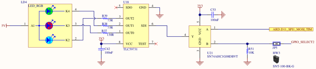
As it is stated in the datasheet, TLC59731 is a PWM based 3 channel (RGB) LED controller with a single wire serial interface based on the EasySet protocol. This protocol also allows to chain an unlimited number of RGB LED devices and control them independently. Every TLC59731 has an output pin that is chained to the next one.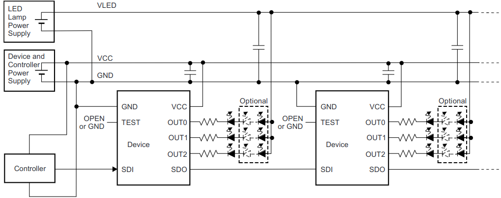
EasySet Protocol
In order to communicate with the RGB controller, the RGB has four stages:
- Data Transfer Rate (Tcycle) Measurement Sequence,
- Data Write Sequence,
- One Communication Cycle End of Sequence (EOS),
- GS Data Latch (GSLAT) Sequence.
Let’s see what tasks each stage is doing.
Data Transfer Rate (Tcycle) Measurement
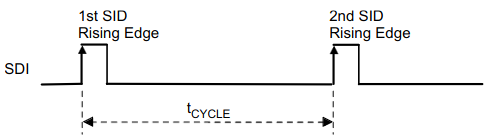 As EasySet is a single-wire protocol without any data synchronization mechanism, we will need a way to know when a single data begins and ends. To do this, TLC59731 measures the time between the first and second SDI rising edges either after the device is powered up or when the GS Data Latch sequence is executed. This time is stored as Tcycle . Tcycle serves as a base time unit used to recognize the other sequences.
Data Write Sequence
If the second SDI rising edge does not appear before 50% of Tcycle elapses from the first SDI rising edge, the second rising edge is recognized as data 0. Otherwise, the second rising edge is recognized as data 1. A second (or third) rising edge must appear at the end of Tcycle.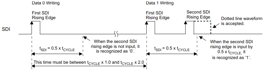
The above pattern should be repeated at least 30 times after the Tcycle measurement sequence to complete a full write sequence (6-bit write command 0x3A followed by 3 8-bit R, G and B channels). If more than 30 bits are transferred, only the last 30 are taken into account. Thus, the Tcycle measurement phase can be included in a write sequence by starting with a 0 bit, for a total of 31 bits. And for convenience, we can also transfer 32 bits, as long as the first bit is zero (the second bit is don’t care).
End of one cycle EOS
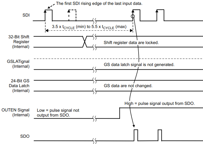 When a write sequence is finished for a LED, the data should be locked and buffered in that LED controller and it should be reconfigured to pass-through so the next TLC59731 in the chain can be programmed. To do this, we should hold SDI low for TH0 (3.5Tcycle to 5.5Tcycle ) . From that point on, the TLC59731 just pushes all the data it receives through to the next device in the chain.
GS Data Latch (GSLAT) sequence
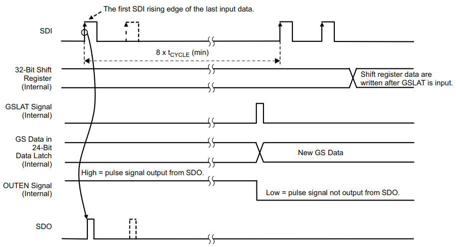 After each full data write command a GSLAT command is required. When SDI is held low for the data latch hold time (TH1 = 8Tcycle), the 32-bit shift register data in all devices are copied to the greyscale (GS) data latch in each device. Since this is just holding the line low for some time, it is implicitly propagated by each device (there are no pulses to propagate). The latch sequence also prepares the devices to receive new data: the next pulse will again be captured by the first device and not propagated through to the next ones, and it will also determine a new Tcycle time.
Writing a device driver in Zephyr
Each device driver in Zephyr has three parts: source (and optionally header) files, a Kconfig file and last but not least, device tree binding files. All driver files are located in the drivers directory. Based on the responsibility of each device, its driver should be placed in the corresponding subsystem directory. LED controllers are normally placed in the drivers/led/ directory. Because the TLC59731 devices can be chained together, however, this is actually a LED strip (even though on our particular board we have only one). Therefore it should be placed in the drivers/led_strip/ directory.
Now, let’s see what exactly each file does.
Driver source files
As its name suggests, a source file contains the implementation of the device driver. The source file name usually is self-explanatory. For example, lpd880x.c says that it is a led driver file for the LPD8803 and LPD8806 family of chips.
Kconfig file
Kconfig files as their name suggests are used for build time configuration of Zephyr. Each Kconfig file contains configuration symbols (options). These options not only specify the configuration, but also they define dependencies between symbols. Symbols can be grouped into menus and sub-menus to keep the interactive configuration interfaces organized. For more information, check the Configuration System (Kconfig) page.
Every driver has its own Kconfig file, e.g. Kconfig.lpd880x. They are sourced in the overall Kconfig file in the subsystem directory.
Device tree binding file
Binding files declare and describe device-specific requirements for the device tree. For example, consider the LED controller example, we need to configure the GPIO pin that is connected to the SDI pin of the TLC59731. A Zephyr device tree binding is a YAML file that defines which properties are required and optional for that particular driver. Zephyr has its own format for the yaml files, it does not use the dt-schema tools used by the Linux kernel. For more information about device tree binding files, refer to the Device Tree Bindings page.
Prepare device driver skeleton
Before diving into device driver development, it may be a good idea to prepare a device driver skeleton. By doing this we will make sure that our device driver is successfully added to the Zephyr build system.
The overall directory of the driver skeleton will be as like this:
Zephyr
├── drivers
│   └── led_strip
│       ├── Kconfig.tlc59731
│       └── tlc59731.c
└── dts
    └── bindings
        └── led
            └── ti,tlc59731.yaml
Based on the above structure, the following file should be created:
tlc59731.c: driver source fileKconfig.tlc59731: configuration fileti,tlc59731.yaml: Device binding file
In addition, the Kconfig and CMakelists.txt files in the drivers/led_strip directory must be updated to include the new Kconfig.tlc59731 and tlc59731.c.
After adding the required files, we should fill them with necessary contents.
Kconfig file
# Copyright (c) 2024 Javad Rahimipetroudi <javad.rahimipetroudi@mind.be>
# SPDX-License-Identifier: Apache-2.0

config TLC59731_STRIP
        bool "TLC59731 LED controller"
        default y
        depends on DT_HAS_TI_TLC59731_ENABLED
        select GPIO
        help
          Enable driver for the Texas Instruments TLC59731 EasySet LED
          controllers.
Let’s see what these magic lines mean.
The config keyword starts a new configuration option on line 4. In our case we are defining a new configuration entry for our RGB controller. The other indented lines are properties of this configuration option. For example, the bool property on line 5 says that the user can either select this configuration or not.
The depends keyword defines the dependencies for this menu configuration. In the above configuration, TLC59731 controller is dependent on DT_HAS_TI_TLC59731_ENABLED which means that the RGB controller should be enabled in the Device Tree. The default y line makes sure that if the RGB controller is enabled in the Device Tree, its driver will also be enabled by default.
The select keyword creates a reverse dependency: if the TLC59731_STRIP option is enabled, we automatically also enable the GPIO option. This makes sure that we enable the GPIO driver, because the TLC59731 driver makes use of it.
Finally, the help keyword is used for adding a brief help to the configuration menu.
Device tree binding file
The device tree binding file is one of the most important files to describe the device hardware configuration requirements. For example, our RGB controller needs a GPIO port for the single-wire interface. As a result, we should add a GPIO property (gpios) in the device tree. The device tree binding file specifies which properties are allowed and expected for the device tree node. The type of the gpios property is phandle-array which means that the details come from another device tree node (i.e. the node corresponding to the GPIO controller). Note that we use plural gpios even though it is only a single one; this is the convention in general for devices that are controlled to a GPIO.
# Copyright (c) 2024 Javad Rahimipetroudi <javad.rahimipetroudi@mind.be>
# SPDX-License-Identifier: Apache-2.0

compatible: "ti,tlc59731"
description: TLC59731 RGB LED Controller

properties:
  gpios:
    required: true
    type: phandle-array
    description: |
      GPIO to send command data to the controller.
  label:
    type: string
    description: |
      RGB Label
Driver Source file
Source files are the most important part of any device driver that implements the driver behavior. Before diving into the driver implementation, let’s first put some place holders and then fill them with actual implementation. The best starting point is using take a look at the device driver standard header file to find out what exactly should be implemented.
As we are going to implement a led_strip device driver, we should look at include/drivers/led_strip.h.
#include <zephyr/types.h>
#include <zephyr/device.h>

#ifdef __cplusplus
extern "C" {
#endif

/**
 * @brief Color value for a single RGB LED.
 *
 * Individual strip drivers may ignore lower-order bits if their
 * resolution in any channel is less than a full byte.
 */
struct led_rgb {
#ifdef CONFIG_LED_STRIP_tlc59731_SCRATCH
	/*
	 * Pad/scratch space needed by some drivers. Users should
	 * ignore.
	 */
	uint8_t scratch;
#endif
	/** Red channel */
	uint8_t r;
	/** Green channel */
	uint8_t g;
	/** Blue channel */
	uint8_t b;
};

/**
 * @typedef led_api_update_rgb
 * @brief Callback API for updating an RGB LED strip
 *
 * @see led_strip_update_rgb() for argument descriptions.
 */
typedef int (*led_api_update_rgb)(const struct device *dev,
				  struct led_rgb *pixels,
				  size_t num_pixels);

/**
 * @typedef led_api_update_channels
 * @brief Callback API for updating channels without an RGB interpretation.
 *
 * @see led_strip_update_channels() for argument descriptions.
 */
typedef int (*led_api_update_channels)(const struct device *dev,
				       uint8_t *channels,
				       size_t num_channels);

/**
 * @brief LED strip driver API
 *
 * This is the mandatory API any LED strip driver needs to expose.
 */
struct led_strip_driver_api {
	led_api_update_rgb update_rgb;
	led_api_update_channels update_channels;
};

/**
 * @brief Update an LED strip made of RGB pixels
 *
 * Important:
 *     This routine may overwrite @a pixels.
 *
 * This routine immediately updates the strip display according to the
 * given pixels array.
 *
 * @param dev LED strip device
 * @param pixels Array of pixel data
 * @param num_pixels Length of pixels array
 * @return 0 on success, negative on error
 * @warning May overwrite @a pixels
 */
static inline int led_strip_update_rgb(const struct device *dev,
				       struct led_rgb *pixels,
				       size_t num_pixels) {
	const struct led_strip_driver_api *api =
		(const struct led_strip_driver_api *)dev->api;

	return api->update_rgb(dev, pixels, num_pixels);
}
Based on this file, there are two api callbacks for led_strip device drivers that should be implemented:
led_strip_update_rgb: To update an LED strip made of RGB pixels,led_strip_update_channels: To update an LED strip on a per-channel basis.
The per-channel update is a low-level access mechanism that usually seems to be unimplemented, so we will not implement it either. So we’ll just implement led_strip_update_rgb. As arguments, it takes an array of color values and the length of the array. On the STM32WB5MM-DK board we have only a single LED so num_pixels should always be one, but in the driver we can support chains of any length.
As the next step, it helps to look at existing deployed device drivers. For this case, drivers/led_strip/ws2812_gpio.c is the best one.
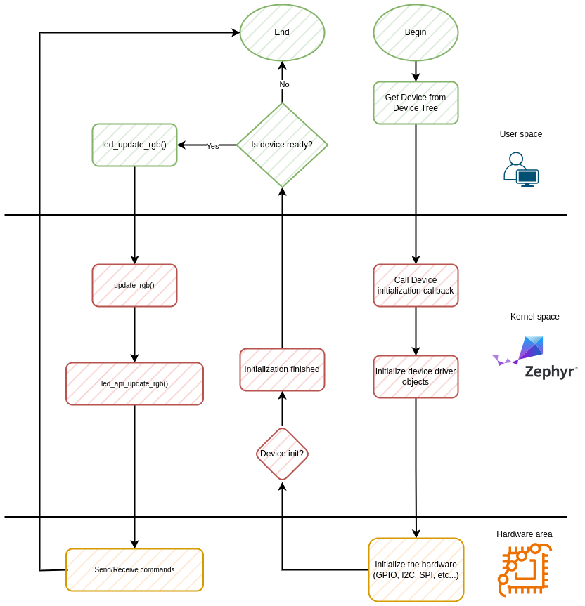
At first glance, it seems too complicated and not too similar to what we need. However, let’s go ahead step by step. First we should understand how device drivers work in Zephyr.
The above flowchart depicts the overall procedure that device drivers follow as a routine. As the first step, we will query the device from the device tree in the user space. This query actually happens at build time. If the device is defined in the device tree and a proper device driver is assigned to it (via the compatible property in device tree, and if the driver is enabled in the configuration), then the struct device* will be filled with the proper data. Otherwise, a linker error (`undefined reference to __device_dts_ord_XX‘, where XX is the device number in the generated device tree file) will be reported. The device driver achieves this with some macro magic in its source file.
Next, the Zephyr kernel will try to initialize the device driver by calling the initialization function callback at boot time. In this function, we will perform all the hardware related stuff. For example, if the device has an I2C interface, we should initialize the I2C subsystem and then send device specific initialization commands to the device over the I2C bus.
At this moment, we can query the initialization status from the userspace code by calling the device_is_ready() system call. If everything goes well, the function will return 0.
For the next step, we can communicate with the device by calling the standard subsystem API. For our device, it will be led_strip_update_rgb. By calling this system call with proper parameters, the Zephyr kernel will call the function callback that we have assigned in the driver source code.
Deploying our device driver
Ok, theoretical concepts are enough. The Zephyr device driver model documentation has a lot more theory, but we are engineers, we learn by doing. Let’s go and do some practical work.
Device configuration structure
Let’s begin with raw materials. No one will be able to build a house without cement, concrete and wood. Similarly we won’t be able to build our device driver with proper data and structures.
What does our RGB controller need? We need to keep track of the GPIO pin used to communicate to the device, and that’s all. We don’t need to keep any state or anything else.
Zephyr’s LED strip driver framework already provides a struct led_rgb structure in led_strip.h. This structure has a config member that we can use for our driver-specific data. So we create a device configuration structure will be as follows:
struct tlc59731_cfg {
	struct gpio_dt_spec sdi_gpio; // SDI GPIO port
};
It will be linked to the parent structure in the device initialization macro.
Device initialization function and macros
Zephyr heavily relies on macros for the driver initialization phase. We will also follow this procedure. First we must define an initialisation function as follows:
static int tlc59731_led_init(const struct device *dev)
{
	const struct tlc59731_cfg *tlc_conf = dev->config;
	const struct gpio_dt_spec *led = &tlc_conf->sdi_gpio;
	int32_t err = 0;
	/* Check whether SDI GPIO is available */
	if (!device_is_ready(led->port)) {
		LOG_ERR("%s: no LEDs found (DT child nodes missing)", dev->name);
		err = -ENODEV;
	}
	/* Set up the GPIO as output port */
	err = gpio_pin_configure_dt(led, GPIO_OUTPUT_ACTIVE);
	if (err < 0) { LOG_ERR("%s: Unable to setup SDI port", dev->name);
		err = -EIO;
	}
	/* T_CYCLE measurement command */
	err = gpio_pin_set_dt(led, LOW);
	if (err < 0) { LOG_ERR("%s: Unable to set the SDI-GPIO)", dev->name);
		err = -EIO;
	}
	gpio_pin_set_dt(led, HIGH);
	gpio_pin_set_dt(led, LOW);

	k_busy_wait((DELAY + T_CYCLE_0));

	return err;
}
However, the world is not as simple as we may consider. There may be multiple chains of RGB LEDs connected to multiple GPIOs. To allow our code to work even in that case, we use a Zephyr helper macro to instantiate the device for each compatible and enabled device node defined in the device tree.
#define DT_DRV_COMPAT ti_tlc59731
#define TLC59731_DEVICE(i)                                                                      \
        static struct tlc59731_cfg tlc59731_cfg_##i = {                                         \
                .sdi_gpio = GPIO_DT_SPEC_INST_GET(i, gpios),                                    \
        };                                                                                      \
        DEVICE_DT_INST_DEFINE(i, tlc59731_led_init, NULL, NULL, &tlc59731_cfg_##i,              \
                              POST_KERNEL, CONFIG_LED_STRIP_INIT_PRIORITY, &tlc59731_gpio_api);

DT_INST_FOREACH_STATUS_OKAY(TLC59731_DEVICE)
DT_INST_FOREACH_STATUS_OKAY will find nodes in the device tree that are compatible with ti,tlc59731 (as defined by DT_DRV_COMPAT, and where commas are replaced by underscores) and call the TLC59731_DEVICE macro for each of them. That macro, in turn, instantiates the configuration structure and uses the DEVICE_DT_INST_DEFINE macro to instantiate the device structure.
RGB update function
Ok, now our device (I hope of course!) is ready to use. We should now implement the API callbacks. As mentioned before, there are two callbacks for led_strip, but we will only implement one of them: update_rgb.
As this callback function is used for a LED Strip, we have num_pixels to update each single RGB LED with its dedicated RGB value. Since our board only has one LED we can test only one of them, but we’ll implement for an entire strip. That means iterating over all the pixels and sending them to the TLC59731 one by one. After each pixel, we have to send an EOS to switch to the next chip in the chain. And after all the pixels have been sent, we have to send a GSLAT to apply the new values simultaneously on the entire chain.
static int tlc59731_gpio_update_rgb(const struct device *dev, struct led_rgb *pixels,
				    size_t num_pixels)
{
	size_t i;
	int32_t err = 0;

	for (i = 0; i < num_pixels; i++) {
		err = tlc59731_led_set_color(dev, &pixels[i]);
		if (err) {
			break;
		}
		err = tlc59731_eos(dev);
		if (err) {
			break;
		}
	}
	if (err == 0) {
		err = tlc59731_gslatch(dev);
	}
	return err;
}
The whole protocol is strictly based on timing between pulses, so the functionality relies on the timing between the different parts of the algorithm. Thus, it has to be looked at as a whole. Still, we’ve split it up into a few functions to clarify how it works.
The EOS and GSLAT phases are simply delays.
static void tlc59731_eos(void)
{
	k_busy_wait(T_H0);
}

static void tlc59731_gslatch(void)
{
	k_busy_wait(T_H1);
}
The set-color function gives the write command for a single LED driver chip:
static int tlc59731_led_set_color(const struct gpio_dt_spec *led_dev, struct led_rgb *tlc59731_data)
{
	const struct tlc59731_cfg *tlc_conf = dev->config;
	const struct gpio_dt_spec *led_gpio = &tlc_conf->sdi_gpio;
	tlc59731_write_data(led_dev, WR);
	tlc59731_write_data(led_dev, tlc59731_data->r);
	tlc59731_write_data(led_dev, tlc59731_data->g);
	tlc59731_write_data(led_dev, tlc59731_data->b);

	return 0;
}
Writing is performed by sending a series of pulses, with varying delays between the pulses:
static inline int tlc59731_pulse(const struct gpio_dt_spec *led_dev)
{
	int fret = 0;

	fret = gpio_pin_set_dt(led_dev, HIGH);
	if (fret != 0) {
		return fret;
	}

	fret = gpio_pin_set_dt(led_dev, LOW);
	if (fret != 0) {
		return fret;
	}

	return fret;
}

static void tlc59731_write_bit(const struct gpio_dt_spec *led_dev, uint8_t data)
{
	tlc59731_pulse(led_dev);

	k_busy_wait(DELAY);

	if (data) {
		tlc59731_pulse(led_dev);
		k_busy_wait(T_CYCLE_1);
	} else {
		k_busy_wait(T_CYCLE_0);
	}
}

static void tlc59731_write_data(const struct gpio_dt_spec *led_dev, uint8_t data)
{
	int8_t idx = 7;

	while (idx >= 0) {
		tlc59731_write_bit(led_dev, data & BIT((idx--)));
	}
}
Userspace demo code
In order to finish our tutorial, I will add a sample demo code to make sure everything is in order. This includes enabling the “chip select” GPIO that feeds the AND gate on the SDI input pin. Then we set the LED to a sequence of colors in a loop.
#define HIGH 1

#define TEST_DELAY 1000 /* ms */

#define STRIP_NUM_PIXELS 1

/* The devicetree node identifier for the chip-select alias */
#define LED0_CS_NODE DT_ALIAS(tlc59731_led_cs)

/* The devicetree node identifier for RGB LED controller alias ('rgbl-led') */
#define LED_CNTRL DT_ALIAS(tlc59731_led)

#define RGB(_r, _g, _b)                  \
    {                                    \
        .r = (_r), .g = (_g), .b = (_b)  \
    }

static struct led_rgb colors[] = {
	RGB(255, 0, 51), RGB(255, 255, 51), RGB(255, 128, 0), RGB(0, 153, 153), RGB(127, 0, 255),
};

#define COLOR_NUM (sizeof(colors) / sizeof(struct led_rgb))

const struct device *tlc59731 = DEVICE_DT_GET(LED_CNTRL);
static const struct gpio_dt_spec led_cs = GPIO_DT_SPEC_GET(LED0_CS_NODE, gpios);

int main(void)
{
	int fret = 0;
	size_t idx = 0;

	fret = gpio_pin_configure_dt(&led_cs, GPIO_OUTPUT_ACTIVE);
	if (fret < 0) {
		printf("Error conf CS pin\r\n");
		return fret;
	}

	/* Enable RGB chip select on the board */
	fret = gpio_pin_set_dt(&led_cs, HIGH);
	if (fret < 0) {
		LOG_ERR("CS Chip Error\n");
		return fret;
	}

	k_msleep(5);

	if (tlc59731) {
		LOG_DBG("Found LED controller %s", tlc59731->name);
	} else if (!device_is_ready(tlc59731)) {
		LOG_ERR("LED device %s is not ready", tlc59731->name);
		return 0;
	}

	LOG_INF("Found LED device %s", tlc59731->name);

	while (1) {
		for (idx = 0; idx < COLOR_NUM; idx++) {
			size_t num_pixels = STRIP_NUM_PIXELS;
			if (idx + num_pixels > COLOR_NUM) {
				num_pixels = COLOR_NUM - idx;
			}
			fret = led_strip_update_rgb(tlc59731, &colors[idx], num_pixels);
			k_msleep(1000);
		}
	}

	return 0;
}
Conclusion
In this tutorial, we developed the simplest, yet complicated enough device driver based on the Zephyr ecosystem. It is still a very simple driver, since it doesn’t need any additional threads or interrupt handling and its API is pretty simple. More advanced drivers will need synchronization primitives like mutexes or queues, and need more advanced memory handling. It is highly recommended to study the aforementioned concepts before developing more complicated device drivers.
You can find the full code for this simple driver in the upstream pull request.
Presentations