
11 Jul Using emulators and fake devices in Zephyr
Using emulators and fake devices in Zephyr

Javad Rahamipetroudi
22/05/2024
Introduction
Just consider that your company is going to use Zephyr for your next project. However, neither you nor the hardware team know exactly which sensors/actuators will be used in the final product, and to make it worse, you do not even know exactly which microcontroller will be used. You want to start developing software before the hardware is available.
The only clear point is that you are going to use Zephyr. Your boss heard that the next-door company is using it and he also wants to add its logo to the company website.
In this case, there are two options available for you:
- Like other people wait until everything becomes clear and the hardware is available and then work days and nights to reach the deadlines.
- Or as a wise person, you say that, ok! At least I know that any device will finally have a processor and some common sensors and display, connectivity, etc. So it will be better to dirty my hand with Zephyr and prepare preliminary things.
In this tutorial as wise embedded engineers, we will also choose the second way and develop a complete application in Zephyr without even using a single piece of hardware.
Zephyr minus hardware
Zephyr provides two simulation approaches to make life easier for engineers:
- Native simulator
- QEMU simulator
In the following section, we will see what these simulators are and what we can do with them.
Native simulator
In simplest words, with the native simulator you generate an executable for your PC, not for a microcontroller. You run it on your PC, natively. So nothing really gets simulated. Some peripherals that are also available on your PC are directly available to the simulated application as well, e.g. display, Ethernet (or rather TCP/IP). For other peripherals (UART, Ethernet, display, I2C bus, …) an emulator driver is used instead of a real driver.
In this simulation, Zephyr uses its Posix Architecture as the target MCU. Since the Zephyr kernel will run on top of the host OS, you also need to simulate time and interrupts and such. The native_simulator creates such an abstraction layer below the Zephyr kernel. As a SW engineer, however, you won’t notice any changes. Everything is handled under the hood.
A major advantage of the native simulator is that it is running natively, so you can use all (or at least most) of the debugging tools you have available on your PC: the debugger, easy integration in an IDE, even tools like valgrind will work to some extent.
Of course, there are some considerable limitations in the Native simulator – in particular if you’re coming from a pure MCU programming background. It is not possible to write to registers directly, you must always use the Zephyr driver abstractions; there are no real interrupts, so code that expects to be interrupted (e.g. an endless loop with no waits in the body) will not work; timing is different so you can’t rely on CPU cycles to advance time in the same way. There are some techniques to overcome such limitations. Generally, these anyway result in code that is better (i.e. more readable and more portable).
QEMU simulator
As its name suggests, in QEMU simulation we compile the application to direct machine-specific binary code. In this case, QEMU emulates the memory layout of the board and runs the same firmware binary that runs on the target device. QEMU simulates the target CPU, including interrupts, timers etc., so the Zephyr kernel runs exactly like it does on a target. QEMU can also simulate some peripherals. For other peripherals, emulated drivers should be used (so the binary is not actually exactly the same as what runs on the target hardware).
As we are using the instruction translation method to mimic the target hardware in our development host, it is slower compared to the Native simulation and sometimes also slower than running on real hardware. However, the simulation is pretty close to the real target architecture.
Which one?
In addition to the POSIX architecture and QEMU, there are other simulation options that come even closer to the hardware: instruction set simulators (that really simulate every instruction instead of translating like QEMU), hardware emulators (that in addition to instructions also emulate the on-chip buses and caches) and even hardware RTL simulation (that simulates the complete chip). All of these offer different trade-off points between speed, debugability, and accuracy of the simulation. The following diagram depicts why we need both of the simulations to have a comprehensive solution for our projects.

(c) The Zephyr Project, Apache-2.0
Based on the diagram, we can compare the two simulation methods based on the Debug visibility (the left-hand diagram) and the Accuracy of the Hardware modelling (the right-hand diagram). In the initial phase of a project, the Native simulator provides full visibility and debugging for the binary image. In this case, we have a better view of what’s happening inside our code.
After finishing the initial phase of deploying the project, we should switch to QEMU-based simulation to have a better view of our project. In QEMU-based simulation, we will make sure that our project is translated to the target architecture language and its behavior is as close as possible to the real hardware.
A simple HVAC system
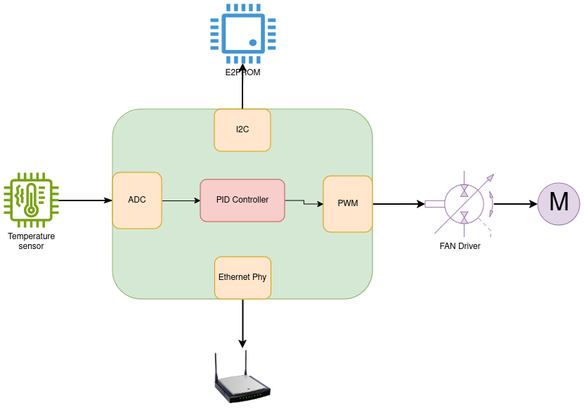
Now it’s time to go and do some tests with all those available options to simulate our project. As we know from our scenario, there is no prior knowledge about the upcoming IoT project. So, we want to develop a simple HVAC system that contains some of the common sensors/actuators of all projects.
For this project, we need the following items:
- A temperature sensor,
- A fan controller (PWM in this case),
- A simple EEPROM emulator,
- Connectivity (Ethernet).
The below diagram depicts the overall HVAC system building blocks. The current temperature is received by the temperature sensor and is read as an analog voltage. Next, the PID controller uses the current temperature to inject the required PWM signal into the FAN driver. We also use simple flash memory to store the device configuration and also a connectivity option to report the system status, etc.
We start with simple things first.
Adding temperature sensor
For the temperature sensor, we assume that it is an analog sensor that produces a temperature-dependent voltage, and that is connected to an ADC for reading out the measurement. Thus, we need to emulate an ADC by adding the zephyr,adc-emul binding into the device tree. As we are going to use native_sim as our simulation platform, we can see that such binding is already added in native-sim.dts:
adc0: adc {
                  compatible = "zephyr,adc-emul";
                  nchannels = <2>;
                  #io-channel-cells = <1>;
                  status = "okay";
          };
Consequently, we only need to define our ADC parameters to use in our board overlay file.
To do this, add native_sim.overlay file to the boards directory of your project and then we configure our boards as follows:
/ {
          zephyr,user {
                  io-channels = <&adc0 1>;
          };
};
&adc0 {
          #address-cells = <1>;
          #size-cells = <0>;
          ref-internal-mv = <3300>;
          ref-external1-mv = <5000>;

          channel@1 {
                  reg = <0>;
                  zephyr,gain = "ADC_GAIN_1";
                  zephyr,reference = "ADC_REF_INTERNAL";
                  zephyr,acquisition-time = <ADC_ACQ_TIME_DEFAULT>;
                  zephyr,resolution = <12>;
          };
  };
Then, we should enable the ADC emulator for the project. To do this, we add the following Kconfig options to prj.conf file:
CONFIG_ADC=y
CONFIG_ADC_EMUL=y
Now we can initialize the ADC peripheral inside our code and use it like any real ADC peripheral. The source code is available on gitlab.
*** Booting Zephyr OS build v3.7.0-rc2-45-g768b8bbca30a ***
fake adc ret: 0
ADC Read val: 1499
Fake EEPROM
As another requirement, we also want to add an EEPROM to our board to store use configurations. For this purpose, we will need an EEPROM device.
Zephyr provides an AT24 EEPROM emulator, so we will use it as our storage system.
Like before we should define the fake EEPROM device inside the project’s device tree. AT24 EEPROMs use I2C bus, we add it to i2c0 node:
  &i2c0 {
          i2c_eeprom: eeprom@57 {
                  compatible = "atmel,at24";
                  reg = <0x57>; class="EnlighterJSRAW" data-enlighter-language="generic" data-enlighter-linenumbers="false"
                  size = <256>;
                  pagesize = <8>;
                  address-width = <8>;
                  timeout = <5>;
          };
  };
Next, we should put the following option into the project configuration file to enable the AT24 emulator for the project:
## EEPROM
CONFIG_EEPROM=y
CONFIG_EMUL=y
CONFIG_EEPROM_INIT_PRIORITY=75
CONFIG_EEPROM_AT2X_EMUL=y
class=”EnlighterJSRAW” data-enlighter-language=”generic” data-enlighter-linenumbers=”false”
Now, we can use it as a real EEPROM device:
*** Booting Zephyr OS build v3.7.0-rc2-45-g768b8bbca30a ***
EEPROM Size: 256
EEPROM WRITE ret: 0
ret: 0, buf: aa, bb
Ethernet connection
Zephyr makes it possible to directly use its network stack to communicate with the development interface. To do this, we need to add a regular connectivity option in the project configuration file:
## ETHERNET
CONFIG_ETH_NATIVE_POSIX=y

# General config
CONFIG_MAIN_STACK_SIZE=1200
CONFIG_POSIX_API=y

# Networking config class="EnlighterJSRAW" data-enlighter-language="generic" data-enlighter-linenumbers="false"
CONFIG_NETWORKING=y
CONFIG_NET_IPV4=y
CONFIG_NET_IPV6=n
CONFIG_NET_TCP=y
CONFIG_NET_SOCKETS=y
CONFIG_NET_IPV4_MAPPING_TO_IPV6=n

# Network driver config
CONFIG_TEST_RANDOM_GENERATOR=y

# Network address config
CONFIG_NET_CONFIG_SETTINGS=y
CONFIG_NET_CONFIG_NEED_IPV4=y
CONFIG_NET_CONFIG_NEED_IPV6=n
CONFIG_NET_CONFIG_MY_IPV4_ADDR="192.0.2.1"
CONFIG_NET_CONFIG_PEER_IPV4_ADDR="192.0.2.2"
class=”EnlighterJSRAW” data-enlighter-language=”generic” data-enlighter-linenumbers=”false”
Then, we should define a bridge adapter to use with the native_sim. Zephyr provides the required tools in a separate repository in <ahref=”https://github.com/zephyrproject-rtos/net-tools” target=”_blank” rel=”noopener”>https://github.com/zephyrproject-rtos/net-tools
After cloning the repository, we should run net-setup.sh script in another terminal. Now everything is ready to set a connectivity inside our code.
For example, in the following demo, we added a network echo server to the project:
*** Booting Zephyr OS build v3.7.0-rc2-45-g768b8bbca30a ***
EEPROM Size: 256
EEPROM WRITE ret: 0
ret: 0, buf: aa, bb
fake adc ret: 0
Eth init finished
Single-threaded TCP echo server waits for a connection on port 4242...
Connection #0 from 192.0.2.2
And we can connect to the native_sim board by telnet:
class=”EnlighterJSRAW” data-enlighter-language=”generic” data-enlighter-linenumbers=”false”
$ telnet 192.0.2.1 4242
Trying 192.0.2.1...
Connected to 192.0.2.1.
Escape character is '^]'.
hello
hello
PID controller
The last part of this tutorial explains how to use our fake device to control the fan speed. So far we were able to read temperature from the ADC, now we want to control a DC Fan motor with a PID controller that regulates the PWM signal.
As we don’t know whether the controller device will have a floating point unit or not, we will use a fixed point PID controller. We reuse the PID controller found online in <ahref=”https://gist.github.com/oldrev/a18c856b77634d0043372393940df224″ target=”_blank” rel=”noopener”>https://gist.github.com/oldrev/a18c856b77634d0043372393940df224
First, we need to initialize the PID controller. Because we read the ADC value in mV integer range. We also allow the PID controller to vary from (-16384, 16383) to cover the whole range.
/****** PID Controller init ********/
FixedPid pid;

FixedPid_Init(&pid);
 class="EnlighterJSRAW" data-enlighter-language="generic" data-enlighter-linenumbers="false"
pid.Dt = Fixed32_FromFloat(0.2);
pid.Max = 16384;// Precent %
pid.Min = -16384;// Precent %
pid.Kp = Fixed32_FromFloat(0.1);
pid.Kd = Fixed32_FromFloat(0.01);
pid.Ki = Fixed32_FromFloat(0.5);
The emulated ADC also needs to be initialized. This has to be done in code that is only enabled in the emulator and not on the real board. There are various ways we can make sure of that, e.g. by defining a board-specific init function, or by protecting it with device-tree-based ifdefs. Since we don’t even have a real board yet, we just include it as part of the application code. We initialize the temperature to 15 degrees centigrade by setting the fake ADC to 1500mV.
We also need to configure a setpoint temperature, which should come through some form of UI. For the time being, we hardcode it to 25 degrees centigrade.
As another initialization for the temperature sensor, we assume that the current temperature is 15 degrees and we want to increase it to 25 degrees centigrade.
fake_adc.input_mv=1500; // 1500 mv as 15 degree
adc_fake_set_value(&fake_adc);
int ftemp = 2500;// Desired temperature; 25 centigrade
class=”EnlighterJSRAW” data-enlighter-language=”generic” data-enlighter-linenumbers=”false”
Now, we can read the temperature from the ADC and then change the PWM duty cycle accordingly. Zephyr doesn’t have a PWM emulator yet (ideally we should add one as part of this project), so for the moment we ignore that part. The PWM should close the feedback loop: increasing the fan speed should eventually cause the temperature to increase. We have to emulate that part as well. For this test, we simply apply the bias directly to the temperature readout.
while (1)
{
      int ctemp = adc_fake_read(&fake_adc);
      printk("ADC Read val: %d\n", ctemp);

      Fixed32 inc = FixedPid_Calculate(&pid, ftemp, ctemp);
      printk("Current Temp: %d, Desired Temp: %d, motor bias: %d\n", ctemp, ftemp, inc);
      /***** Change the PWM based on calculated error ******/
      /* This section omitted. */
      k_msleep(10);

      /* Here we assume the temperature is changed due to FAN speed */
      fake_adc.input_mv = ctemp + inc;
      adc_fake_set_value(&fake_adc);
}
By running the binary application, we observe a gradual change in temperature until it reaches the desired level.
*** Booting Zephyr OS build v3.7.0-rc2-45-g768b8bbca30a ***

Current Temp: 1499, Desired Temp: 2500, motor bias: 250
Current Temp: 1748, Desired Temp: 2500, motor bias: 237
Current Temp: 1984, Desired Temp: 2500, motor bias: 265
Current Temp: 2248, Desired Temp: 2500, motor bias: 262
Current Temp: 2509, Desired Temp: 2500, motor bias: 235
Current Temp: 2743, Desired Temp: 2500, motor bias: 189
...
Current Temp: 2500, Desired Temp: 2500, motor bias: 1
Current Temp: 2500, Desired Temp: 2500, motor bias: 1
Current Temp: 2500, Desired Temp: 2500, motor bias: 1
Current Temp: 2500, Desired Temp: 2500, motor bias: 1
We have now used the emulator to be able to develop software before the hardware is available. It will remain useful even when the hardware is available, to be able to test the application code without hardware in the loop. It is much easier to reliably create corner cases in the emulator, like very high or very low temperatures, or a broken motor.
Conclusion
In this tutorial, we aimed to demonstrate Zephyr’s capability in deploying comprehensive firmware without requiring in-depth knowledge of the underlying hardware. While we utilized pre-built emulators, it’s worth noting that Zephyr offers ample support for integrating new emulation devices as needed.
Presentations