

Introduction
In contrast with other tutorials, this tutorial is not directly related to Zephyr OS. However, it is an important preliminary step which helps us to have a better understanding of Bluetooth (BT) devices. In this tutorial we are going to review the BT module (STM32WB5MMG) that is already mounted on the B-U585I-IOT02A board. Next, we will try to update its firmware and then we will implement a simple demo application on the board.
STM32WB5MMG Bluetooth module
STM32WB5MMG is a low power Bluetooth Low Energy (BLE) module which supports Bluetooth 5.4, Zigbee and OpenThread modes. Even though we can consider it as a Bluetooth module, it provides all required tools to deploy a complete Bluetooth application without need for an additional, external microcontroller.
Let's take a look of the module’s internal architecture:

As we can see, the module contains all required components for handling the wireless communication, including a small footprint PCB antenna.

The module is built around the STM32WB55VGY chip. It is a dual core multi-protocol wireless microcontroller. The core wireless functionality is handled on a small ARM Cortex M0+ core (CPU2) and dedicated hardware to handle the PHY functions. The second core is a full-featured Cortex M4F processor (CPU1) with many peripherals and external interfaces that you need to build a full-featured application. To understand better how these two cores work together, we can split the whole functionality over which parts are handled on which core. CPU2 runs the wireless firmware and exposes certain interfaces to CPU1. CPU1 can then run application code to interact with the wireless stack.


As we mentioned above, the STM32WB55VGY microcontroller supports different wireless stacks: BLE, 802.15.4/OpenThread, and 802.15.4/Zigbee. This is quite low-level and closed source firmware. As a result, we should program CPU2 with the proper firmware binary based on the type of our requirements. The binaries are distributed as part of STM32CubeWB (on github).
The binaries directory contains release notes that describe the function of each binary. For example, in BLE mode, the stm32wb5x_BLE_Stack_full_fw.bin firmware provides the following features:
- GAP peripheral, central (Master up to 8 links/Slave up to 8 links/all combinations in between)
- GATT server, client
- Data length extension
- 2Mbit PHY / PHY update
- Privacy
- White list
- Legacy Pairing, LE secure connections
- Direct Test Mode
- HCI interface (full, like
stm32wb5x_BLE_HCILayer_fw.bin)
For the next step, we are going to install/update the CPU2 firmware.
Updating CPU2 firmware
Installing required tools
In order to update CPU2 firmware, you should download the STM32WB5x firmware package and the STM32CubeProgrammer must be installed.
The firmware package should be extracted in a location. We assume in the examples here that it is located in ~/STM32Cube/Repository/STM32Cube_FW_WB_V1.18.0, you can easily adapt to your own location.

Jumper setting on the development board
There are different ways to upgrade the Bluetooth module of the B-U585I-IOT02A board. However, the easiest way is using the STLink programmer that already exists on the development board. By default, it is connected to the STM32U5858 microcontroller. But it is possible to connect it to the Bluetooth module by changing the SW4 and SW5 states. To do this, you should put the SW4 in OFF mode and SW5 in ON mode. After upgrading the STM32WB55xx module, put them back to the default state.
Upgrading the Bluetooth module
Now everything is ready to upgrade the Bluetooth module. To do this, open the STM32CubeProgrammer and click on the connect button. If it connects correctly, you will see the Device information in the Target Information box that is located on the right bottom side of main window.
 Check in the Target information (bottom right) that you’re indeed connected to the STM32WB5x and not to the main microcontroller. Next, go to the Firmware Upgrade Service from the left side menu:
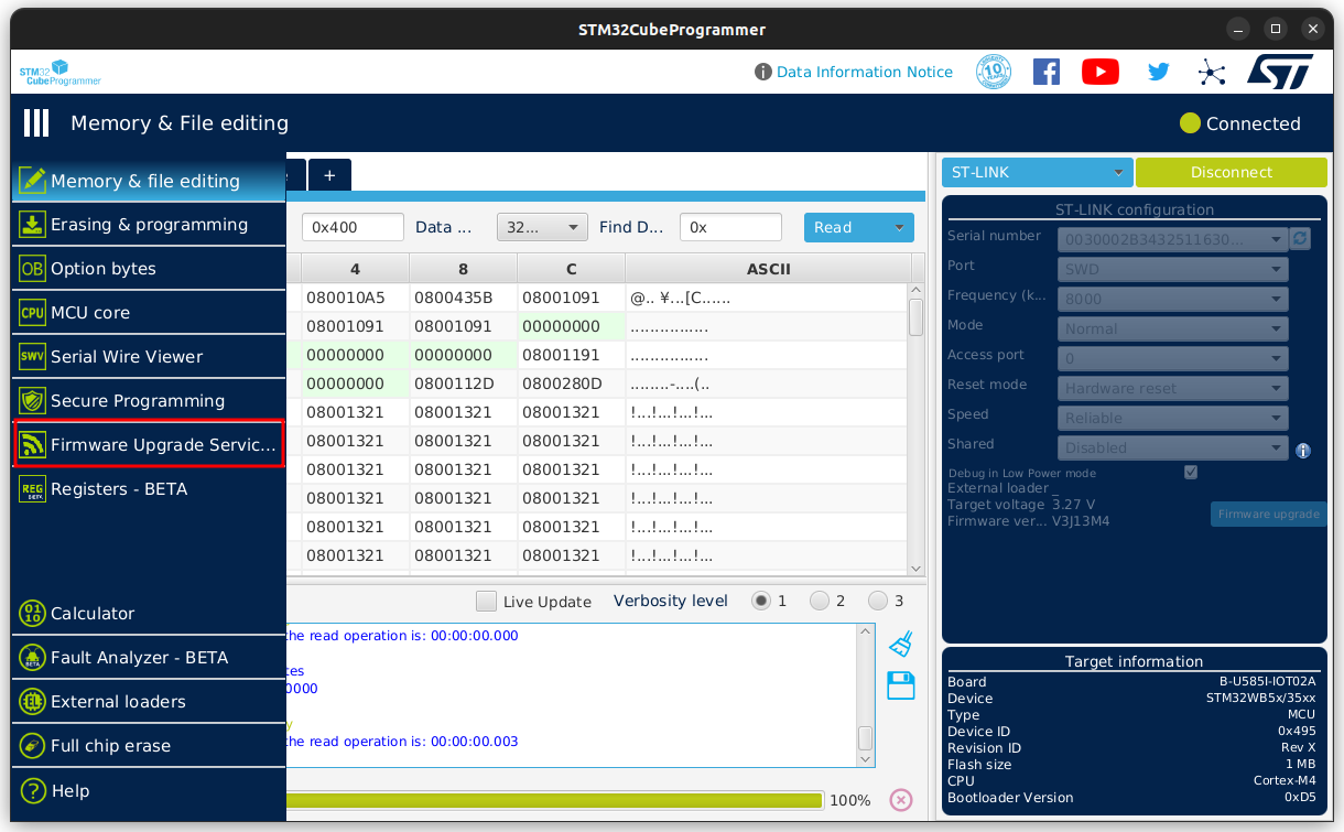
Select the proper firmware
Selecting the right firmware depends on the type of application that we are going to develop. All the firmware binaries are available in STM32Cube_FW_WB_V1.18.0/Projects/STM32WB_Copro_Wireless_Binaries/STM32WB5x directory. The Release Note page (Release_Notes.html) in this directory contains all the information that we need to update the firmware.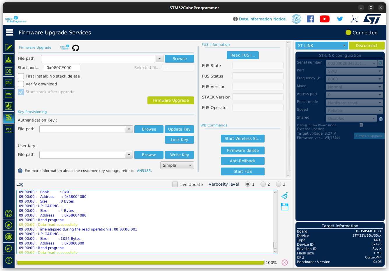
The firmware update process has two parts. The first part is Firmware Upgrade Services (FUS) that is responsible for upgrading the Wireless Coprocessor (CPU2). However, before upgrading the FUS firmware, it is better to check the installed firmware version. To do this click on the Read FUS button from FUS information box. As it is mentioned in the Release Notes, if the FUS version is higher than v1.2.0, no update is required.

To update the Wireless Coprocessor firmware, we choice stm32wb5x_BLE_Stack_full_fw.bin that is the one of the complete firmware based on the release notes. Please note that any firmware has a dedicated start address. As a result, before updating the firmware, we should select the proper starting address from the Wireless Coprocessor Binary Table based on the type of the firmware and device in the release note page.
As we are using stm32wb5x_BLE_Stack_full_fw.bin on the STM32WB5xxG(1M) device, the starting address will be 0x080CE000
For the next step, click on the Start FUS , then click on Browse from the Firmware upgrade box:

Then, choose stm32wb5x_BLE_Stack_full_fw.bin from the File window. Furthermore, the proper Start Address should be placed in Start address textbox. Last but not least, the Verify download should also be checked. By clicking on the Firmware Upgrade button, the upgrade will be begin.
If everything goes well, we will see the Firmware Upgrade Success message in the Log box.
Flashing the CPU1 with a demo firmware
To test the module, we should install a demo application on CPU1 and see how it is working. Several example applications are provided with STM32CubeWB. They are, however, mostly targeted to the NUCLEO-WBA55CG development board. We have to use an application that will also work on the B-U585I-IOT02A board, which has no peripherals connected to the STM32WB55xx at all. Therefore, we use the AT client/server from the firmware development package, where the AT server is installed on CPU1 of the STM32WB55xx and we can run the AT client on a PC connected to the debug port.
The AT server binary firmware is available at STM32Cube_FW_WB_V1.18.0/Projects/P-NUCLEO-WB55.Nucleo/Applications/BLE/BLE_AT_Server/Binary
But if you flash the above firmware in CPU, it will disable the SWD module that is used by STLink. Therefore, next time you want to connect to the Bluetooth module, you will need to hold the Bluetooth Reset button and then click on connect in STM32CubeProgrammer.
To flash the device, go to Erase & Programming section and select the binary from the Download box and then click on Start Programming - no start address needs to be provided for the CPU1 firmware.

The AT Client program is available in STM32Cube_FW_U5_V1.4.0/Projects/B-U585I-IOT02A/Applications/BLE/BLE_AT_Client
It can be built and loaded on the B_U585i board with STM32CubeIDE.
After flashing the board, connect to the virtual serial port that is exposed on your PC by STLink. You will see the AT commands send and receive sequences:
TX: AT
TX: AT+BLE_SVC=1
RX: OK
RX: <BLE_EVT_CONN=1
A remote device is  now connected